

Electrical phenomena: Surge and Burst
Ben Winstanley • November 8, 2019
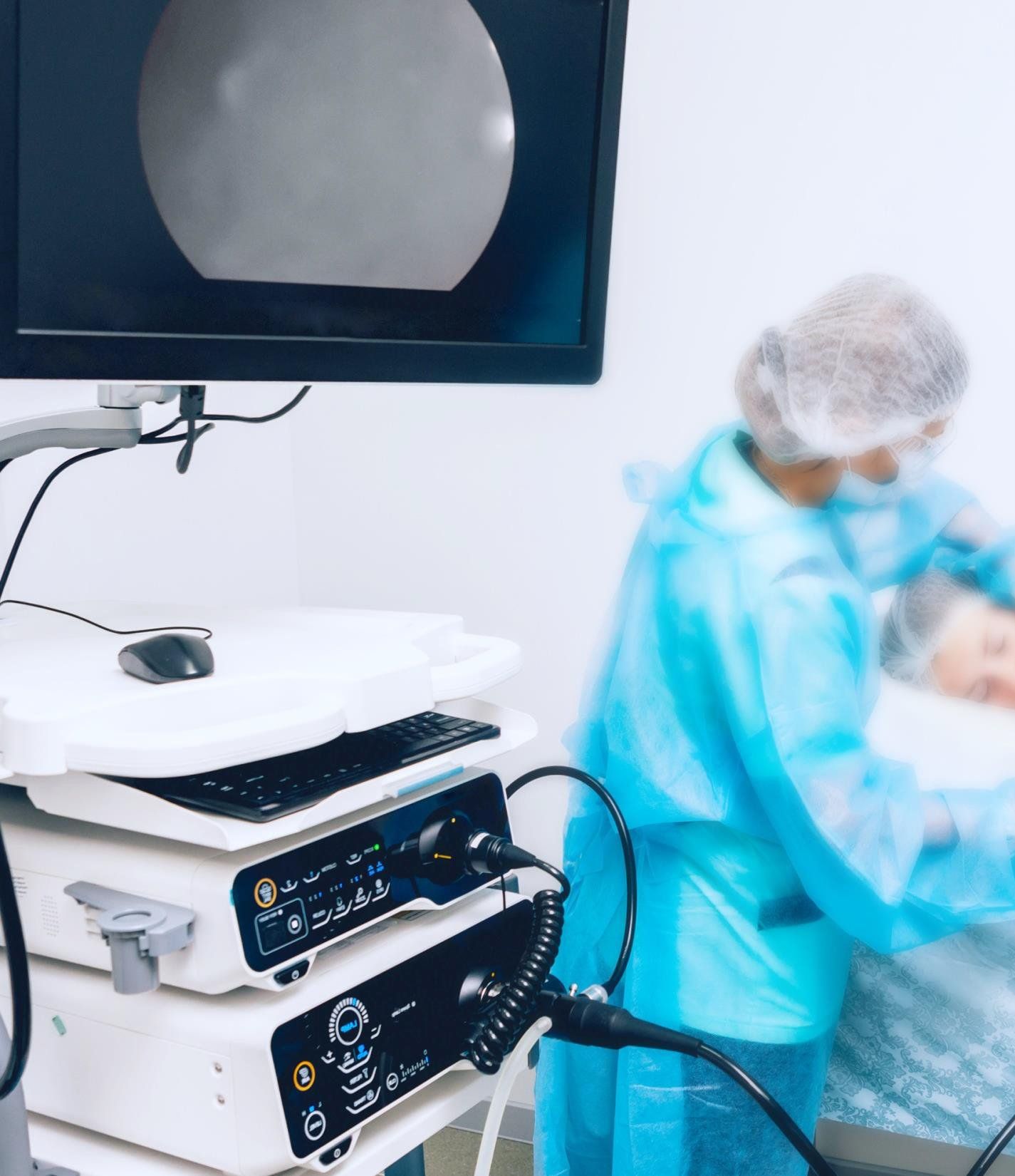
Heart failure: one of the worst incidents in medicine. If the heart fails, everything fails!
The same applies to the power supply of an application: If its performance is unreliable, the entire system is paralyzed - which can have the worst conceivable consequences in medical technology. Examples range from malfunctioning instruments and apparatus in the midst of a complicated operation to a possible worst-case scenario such as the unintentional cessation of life-support measures,
It is therefore important, especially for medical power supplies, to strive for the highest possible reliability and to guard against any incidents. Two possible interference factors are the phenomena "surge" and "burst", for which the corresponding interference immunity is regulated in the IEC 61000-4 standards. This article fundamentally describes the phenomena mentioned as well as the immunity to be complied with according to the applicable standard, and gives some tips for the practical implementation in engineering as well as for the selection of a suitable power supply.
Overvoltage and its impacts
“Overvoltage" describes an electrical voltage which exceeds the permissible tolerance range of an electrical system’s nominal voltage. For an electrical device, the phenomenon sometimes has a destructive effect of key significance: The excess energy can destroy components of the electrical circuit and can cause errors and equipment failures. It is therefore of utmost importance to consider the immunity against possible occurring overvoltage when engineering a power supply.
But when does a so-called overvoltage actually occur? Within the European AC voltage grid, the rated voltage according to EN 60038 is 230 V with a tolerance of +/- 10 % in single-phase systems. Thus, voltages of more than 253 V are to be considered as overvoltage in our power grid by definition. Such overvoltage can either occur permanently, for example because of a faulty electrical installation, or for a short time, due to bolts of lightning or switching operations.
While the protection of a device against permanent overvoltage would be possible only with extreme effort and is also unnecessary because of the rare occurrence within a typical AC grid, short-term overvoltage is quite more common than expected and requires appropriate safety measures. The overvoltage can occur both symmetrically between the electrical conductors as well as asymmetrically between electrical conductors and earth.
In general, one distinguishes two phenomena of short-time overvoltage, which, in accordance with the corresponding standards, should be examined more closely:
1. Surge
2. Burst
Surge according to IEC 61000-4-5
The phenomenon of surge voltage is regulated in IEC 61000-4-5. This standard describes the "Immunity test of electrical and electronic equipment, devices and installations against shockwaves (surge voltages and currents)" and was adopted in March 2015 in its current version.
In a power grid, short-term surge is caused by a wide variety of events. A fundamental distinction is made between surge caused by switching operations or system errors, and overvoltage caused by lightning. The latter does not only apply to direct lightning strike to a power grid, but also to indirect lightning strikes and induced currents to the ground or earth system of a complex nearby.
Surges occur more frequently than expected
Even the mere number of yearly lightning strikes illustrates how often we encounter short-term surge voltage in a power grid: last year, over 450,000 lightning flashes hit Germany, which – depending on the location – had a corresponding impact on our power grid. This number seems relatively low in comparison to previous years: in 2015, for example, 550,000 flashes were noted, in the stormy year 2007, a record level was recorded with about 1.1 million flashes. Added to this are the countless switching operations, which are currently increasing due to a switch from centralized to decentralized power grid (smart grid), as well as other influencing factors which can also lead to high pressure on the power supply for a short time.
Standard-compliant simulation of surges
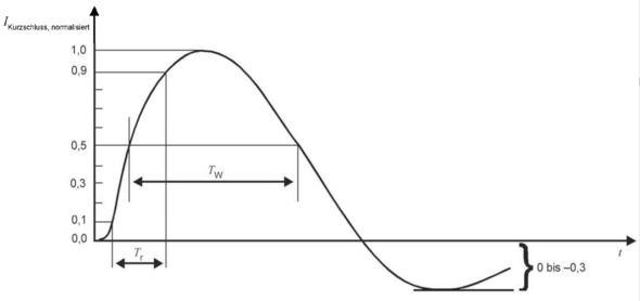
In general, a surge is a momentary, very high-energy pulse, which the device must survive unscathed. To simulate such a surge, a generator is used to simulate the pulse shape of the phenomenon. The standard underlying pulse form for surges has a wave-front duration of 1.2 μs with a pulse duration of 50 μs (1.2/50 μs) for the no-load voltage and a wave-front duration of 8 μs with a pulse duration of 20 μs (8/20 μs) for the short-circuit current.
Specifically for outdoor telecommunications, the standard requires higher pulses of 1.2/50 μs for the voltage and 5/320 μs for the current. These pulse forms represent the specific characteristics of a telecommunications network. Other standards also contain further pulse forms such as 10/1000 μs.
Medical applications and devices are typically located in buildings and are therefore tested with a pulse definition of 1.2/50 μs and 8/20 μs for the power supply.

The different test severity levels are now set by the peak value of the open circuit voltage. IEC 61000-4-5 defines values for four different severities. The degree of severity required for a device depends on various factors and is specified in the corresponding product standard of the electrical devices. In medical technology, this means EMC safety standard IEC 60601-1-2 in its 4th edition. Electrical appliances of protection class II to be used in buildings must have an interference immunity to surge of severity level 3. This also applies to medical-electrical appliances, both in the hospital environment and in the so-called home healthcare environment.
Since the surge can occur between supply lines as well as between supply lines and earth, different types of input coupling exist in addition to the different voltage peaks:
As far as surges between conductors are concerned, low impedance and high energy can be assumed, also called "differential mode". The coupling impedance corresponds to the generator’s internal resistance and is specified with 2 Ω. The energy is transferred via an 18 μF coupling capacitor.
"Common mode" applies to pulse voltages between conductors and earth. In this case the impedance is higher and reads 12 Ω (2 Ω generator internal resistance + 10 Ω due to poorer conducting earth). The energy is transmitted via a 9 μF coupling capacitor, but the voltage level is twice as high as in the "differential mode”.
Communication lines have different impedances than supply lines, which is why other impedances are used. Frequently one encounters values of 25 Ω or 42 Ω.
| Test severity | No-load voltage kV | |
|---|---|---|
| lead – lead | lead – earth | |
| 1 | - | 0,5 |
| 2 | 0,5 | 1 |
| 3 | 1 | 2 |
| 4 | 2 | 4 |
| X | Special definition | Special definition |
Test severities for surges (IEC 61000-4-5)
Protection against surges
There are different methods to protect devices against destruction by surge. The simplest way is to match the affected components such as diodes and capacitors with the appropriate voltage. At higher test voltages, however, this is no longer possible, which is why components are required which limit the voltage within the device. This is done by using varistors (VDRs) or gas discharge tubes which become conductive at a certain voltage and convert the surplus energy into heat. Gas discharge tubes are not permitted for every application. Since these components not only have a voltage-limiting effect, but short-circuit the circuit when the breakdown voltage is reached, they may only be used in DC circuits. They should not be used in AC supply lines, since a short-circuit in a supply line leads to a long-lasting high current, which can also trigger the house’s main fuse and shut down the power supply for all devices permanently. Consequently, VDRs are used for AC supply lines.
Burst according to IEC 61000-4-4
Transient disturbances are caused by brief switching operations, such as the disruption of inductive loads or the bouncing of relay contacts in a power supply grid as well as in control and signal lines. These disturbance variables are voltage peaks which are coupled in lines in so-called “bursts”. Characteristic are the high amplitude, the short rise time, the high repetition rate and the low energy of the transients.
")
Immunity test of bursts
The handling of this phenomenon is fundamentally regulated in the IEC 61000-4-4 standard: "Immunity test against fast transient electrical disturbances/burst". In its current version of April 2013, the standard specifies the repetition rate to be tested for the transients at 5 and/or 100 kHz, with the actual value of the burst phenomenon being closer to 100 kHz. The test specification 5 kHz still dates back to a time when the test equipment was incapable of producing transients with such a high repetition rate.
The coupling of the fast transients is carried out during the test either by means of a coupling capacitor directly applied to the supply lines, or indirectly via a capacitive coupling pliers to control and signal lines. The degree of severity to be maintained in the burst is ultimately determined in the respective product standard of the device, for medical devices degree 3 applies.
| Test severity | No-load voltage kV | |
|---|---|---|
| Power connectors, earth connectors (PE) | Signal and control connectors | |
| 1 | 0,5 | 0,25 |
| 2 | 1 | 0,5 |
| 3 | 2 | 1 |
| 4 | 4 | 2 |
| X | Special definition | Special definition |
Test severities for bursts: (IEC 61000-4-4)
In general, burst pulses are not as destructive as surge pulses. However, they often lead to unwanted behavior of devices, which can surface, for example, in form of flickering displays or incorrect circuit measurements. At very high amplitudes, a device can ultimately be destroyed. The general problem with burst pulses is that they can only be filtered out to a very limited extent. In this case, a VDR is only of limited protective suitability since the response time of these varistors is too long. In contrast, the use of fast suppressor diodes can serve as a possible solution.
Selection of adequate power supply
Purchasers and engineers should focus on compliance with the IEC 61000-4-4 and IEC 61000-4-5 standards when selecting the appropriate power supply for their application, to protect their application from the destructive effects of the phenomena ”surge and burst”. These standards must be enforced by all standard medically approved power supplies in accordance with IEC 60601-1-2, so users initially consider themselves on the safe side.
However, especially for particularly safety-critical applications, such as patient monitoring systems or life-sustaining systems, the values required by the standard should rather be considered pedestals. Here it is recommended to examine the application and its corresponding safety precautions together with a power supply expert in order to achieve the best possible interference immunity - at FRIWO, for example, with designs of up to 6 kV surge resistance.
[1] Siemens AG: Blitzatlas 2017, www.elektroniknet.de/elektronik/power/die-3-blitzreichsten-regionen-deutschlands-156217.html
CONTACT US
COMMENT ON THIS POST
SHARE THIS POST
While you're here, why not read some of our other blog posts?
We are 99% sure you'll learn something!
High-Efficiency Medical-Grade Open Frame Power Supplies

Meet Mr NEO! The New Face of Our Power Supply Solutions!
Your Guide To Selecting The Ideal Charger
If you're wondering how o find the power power supply, check out this guide to help make your decision simple!
Why is power so important for medical devices. Join us as we explore what makes power supplies, batteries and chargers so important for medical devices.
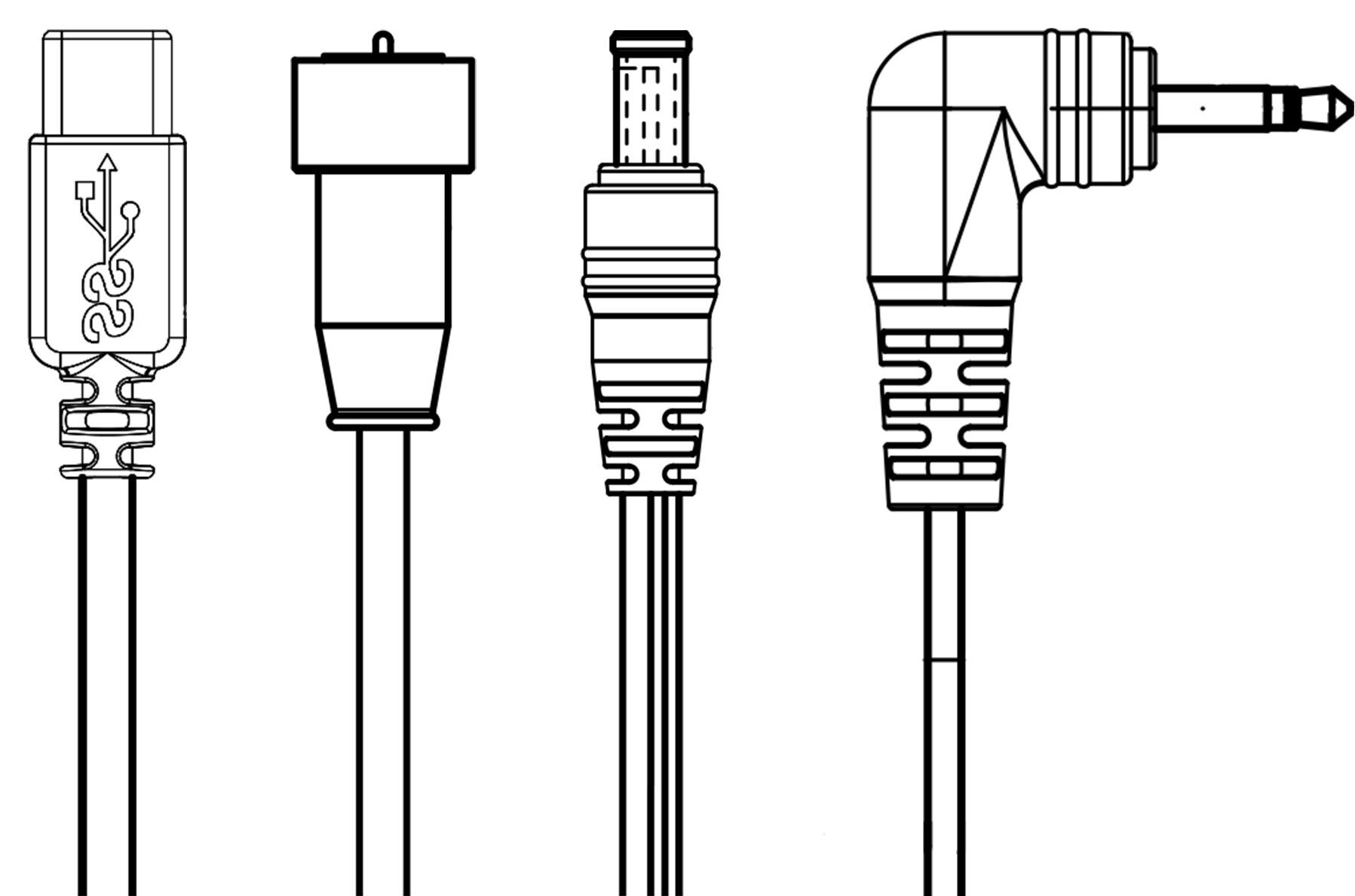
Join us for a deep dive into the pros and cons of Direct Current (DC) connectors. have a project that requires a DC connector? Find your perfect match here!
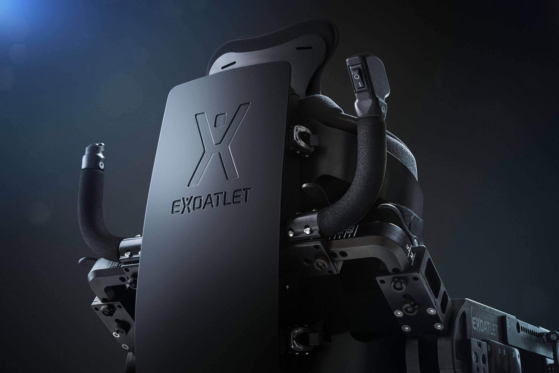
INDEPENDENT POWER SUPPLY FOR MEDICAL EXOSKELETONS A FRIWO systems solution in practice Finally being able to walk again. ExoAtlet, the renowned medical technology company, wants to grant that exact wish to its patients with physical disabilities. The specially designed and built exoskeleton allows people who have been confined to a wheelchair to stand freely, and without assistance, for the first time since their disability – and not only stand, but walk! The “ExoAtlet II” skeleton allows the wearer to move at different speeds as well as across different types of terrain without being hindered by stairs or other obstacles.
Selection and operation of a battery charger
Switchmode Power Supplies vs Linear Power Supplies
The vast majority of low voltage external power supplies sold globally these days are switching (switchmode) units, as opposed to the original Linear technology, which is only considered appropriate for certain niche markets due to it’s inability to meet required efficiency standards.
In this article we will explore just some of the technical aspects & features and benefits of Switchmode topology vs Linear.
